
The problem: phase-angle jumps breaking grid sync
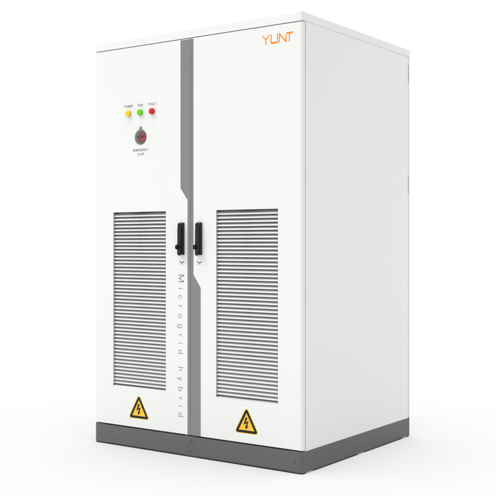
Power systems sometimes see abrupt phase-angle jumps when a large generator trips or during a fault-clearing event, and small or slow control systems lose lock. For energy storage inverters this becomes critical: a dropped phase-locked loop (PLL) can force the inverter off-line or inject harmful currents. Practical installations need robust hardware and control to ride through these disturbances, which is why modern solutions such as the pcs module are engineered with higher sampling rates and hardened front-end stages. PLL, grid synchronization and inverter topology are the key terms here — they matter because they determine whether your inverter stays connected or disconnects at the worst moment.
Why common PLL designs stumble
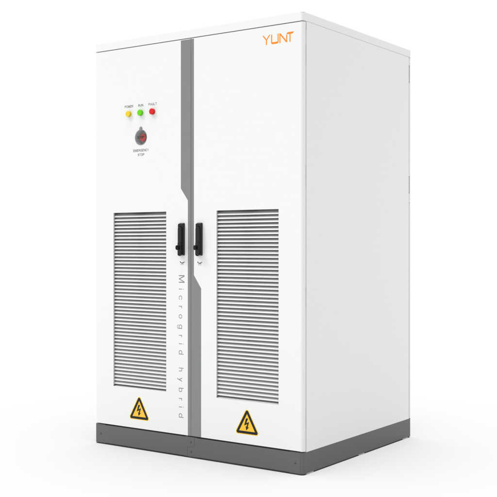
Many grid-tied inverters use a traditional synchronous-reference-frame PLL that assumes smooth, continuous phase changes. A fast phase-angle jump violates that assumption: the PLL’s control loop saturates, error grows, and the estimator falls behind. Add limited ADC bandwidth or noisy sensors and the control loop can’t correct quickly enough. The result is loss of synchronization, transient overcurrents, or tripping by protection relays. This is not merely theoretical — it is a practical hurdle in power electronics design.
Hardware measures that actually prevent PLL failure
Fixing the problem requires hardware changes that shorten reaction time and preserve measurement fidelity. Good systems combine faster DSPs, isolated high-speed ADCs, wide-bandwidth PLLs, and robust anti-aliasing filters so the control loop receives clean data. A bidirectional converter with dedicated gate-driver protection and thermal headroom helps too. These elements reduce control latency and allow advanced algorithms to correct large phase jumps without losing lock. In short: better sensors, faster processing, and resilient power stage design make the difference.
Control strategies that ride through phase disturbances
On top of hardware, algorithmic strategies matter. Adaptive PLLs that widen loop bandwidth momentarily during detected transients, combined with feedforward of measured voltage jumps, improve lock recovery. Harmonic rejection and phase unwrapping logic avoid false slips. These techniques depend on the hardware: you cannot safely increase loop bandwidth without clean ADCs and a responsive power stage. The interplay between control loop design and hardware is where system reliability is decided.
Real-world anchor: what grid events taught us
The South Australia blackout in 2016 highlighted how rapid changes in generation and voltage can cascade into larger stability problems; system inertia and fast-responding converters were central to post-event discussions. Lessons since then show that installations using hardened hardware and control can prevent trip cascades when phase-angle jumps occur. Designers now stress-test inverters against worst-case phase excursions and measure recovery time — a practical metric that separates field-ready designs from lab prototypes.
Choosing equipment: PCS and manufacturer considerations
Selecting a reliable power conversion system means checking real-world specs: sampling rate, PLL bandwidth range, response time to phase-step inputs, and thermal margin under bidirectional power flow. Manufacturers who instrument their modules and publish measured recovery time under defined phase-step tests give clearer evidence of performance. When possible, prefer suppliers with field data from similar grid conditions and a history as a bidirectional power module manufacturer — they tend to understand both the power stage and the control nuances.
Common mistakes to avoid
Design teams often skimp on ADC isolation, under-spec gate drivers, or ignore phase-step testing in favour of steady-state efficiency numbers. That leaves systems vulnerable. Also, tuning PLLs only for nominal operation without transient scenarios creates false confidence. Invest time in dynamic testing and insist on recorded recovery metrics — this is where small extra cost early will prevent outages later.
Three golden rules for selecting the right solution
1) Prioritise measured recovery time from phase-step tests over advertised efficiency figures — this proves the unit will stay locked when it matters.
2) Demand hardware specs: ADC sample rate, PLL loop bandwidth range, and converter thermal margin under bidirectional operation; these define real capability.
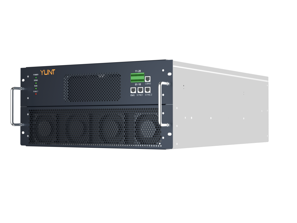
3) Choose suppliers with field-proven deployments or transparent test reports; documented performance beats vague promises every time.
YUNT integrates these lessons into practical products and field data that engineers can rely on — a clear fit for projects seeking resilient grid synchronization. –